| MECHANICAL SPECIFICATIONS |
| Materials |
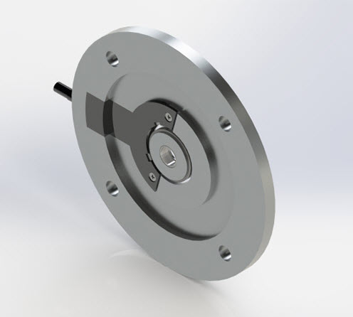
Flange: Aluminium
Hub material: Stainless Steel
Magnet Ferrite |
| Maximum number of revolutions permitted mechanically |
6000 rpm |
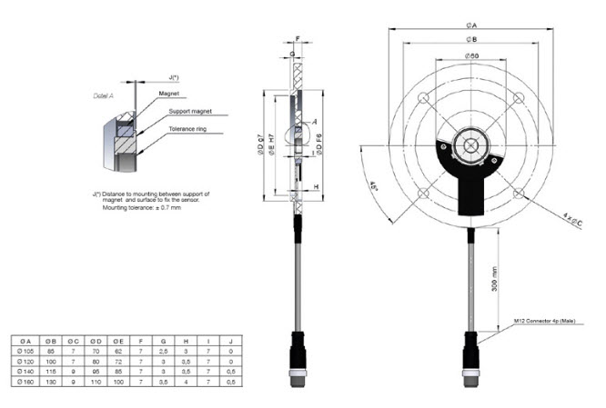
| Shaft diameter |
11, 14, 19 mm |
| Housing fixing |
4 holes (see dimensions table Ø B – Ø C ) |
| Permitted misalignment |
±0.7 mm axial, ±1 mm radial |
| Protection against dust and splashes according to DIN EN 60529 |
IP67 |
| Weight aprox. |
0,4 Kg |
| Operating temperature range |
-20ºC to +85ºC |
| Vibration according to DIN EN 60068-2-6 |
100 m/s2 (10Hz…2000Hz) |
| Shock accoording to DIN EN 60068-2-27 |
1000 m/s2 (6ms) |
| Axial or radial connection |
30 cm cable ended with M12 4p industrial male connector
Female connector not included |